Systems Overview
This section introduces the main systems being restored and modified as part of the project.
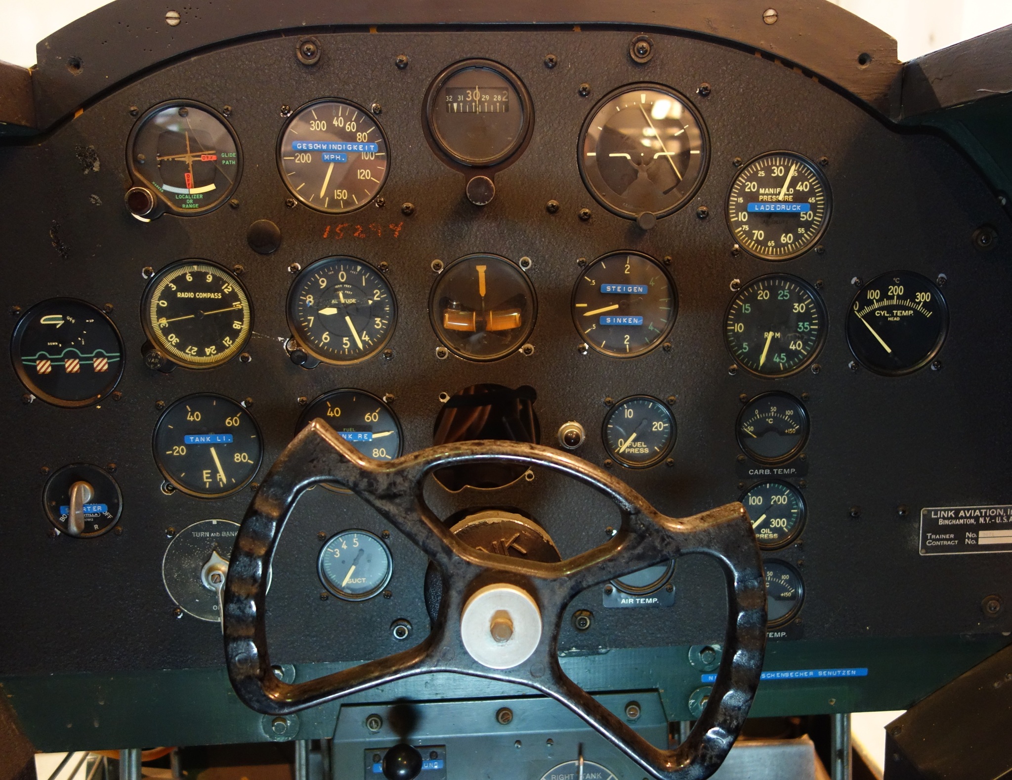
Instruments
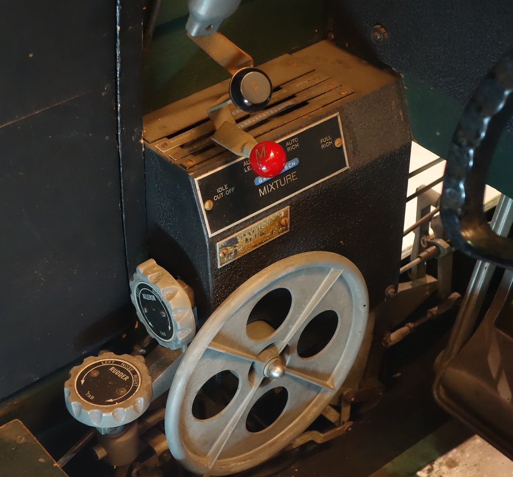
Throttle, Mixture & Trim
A closer look at the left side of the cockpit, featuring the throttle controls, mixture control, and trim system used for aircraft handling and engine management.
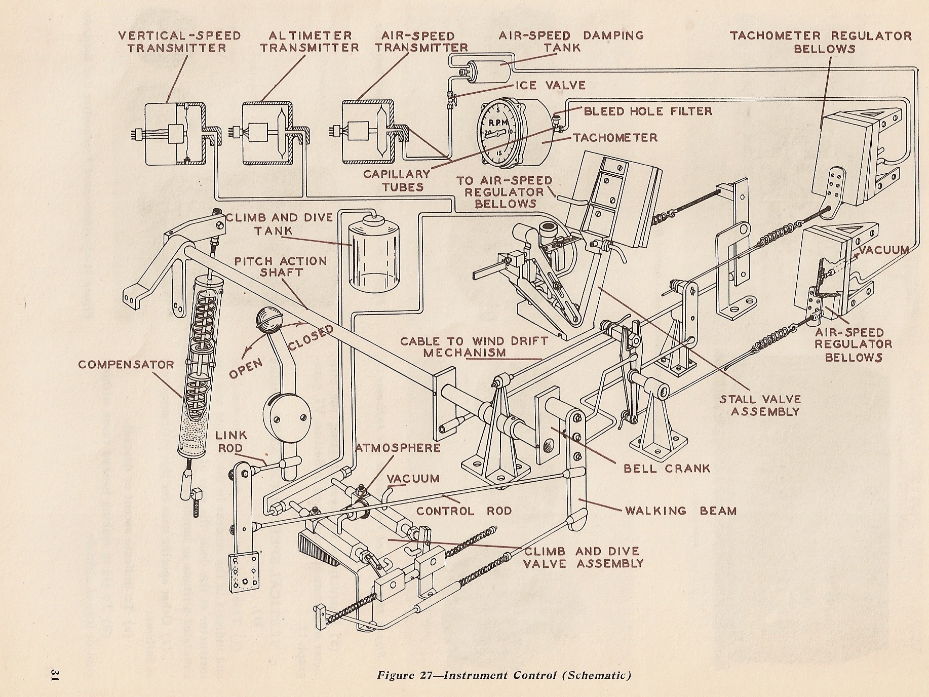
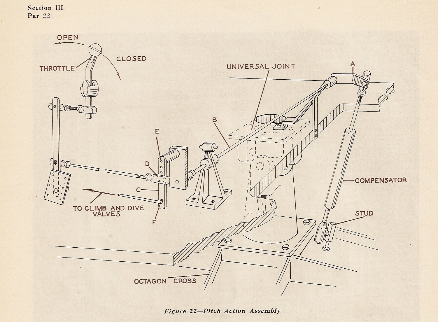
In the original Link Trainer design, throttle position and nose-up or nose-down movement mechanically controlled a series of vacuum-operated valves and regulating bellows. These systems generated realistic indications for instruments such as the altimeter, vertical speed indicator, airspeed indicator, and tachometer.
It is a fascinating example of how complex aircraft systems and flight behavior were simulated long before the age of digital electronics and computers
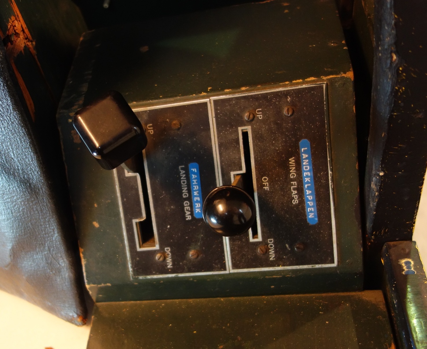
Flaps & Landing Gear
The flap and landing gear controls are located to the left of the seat.
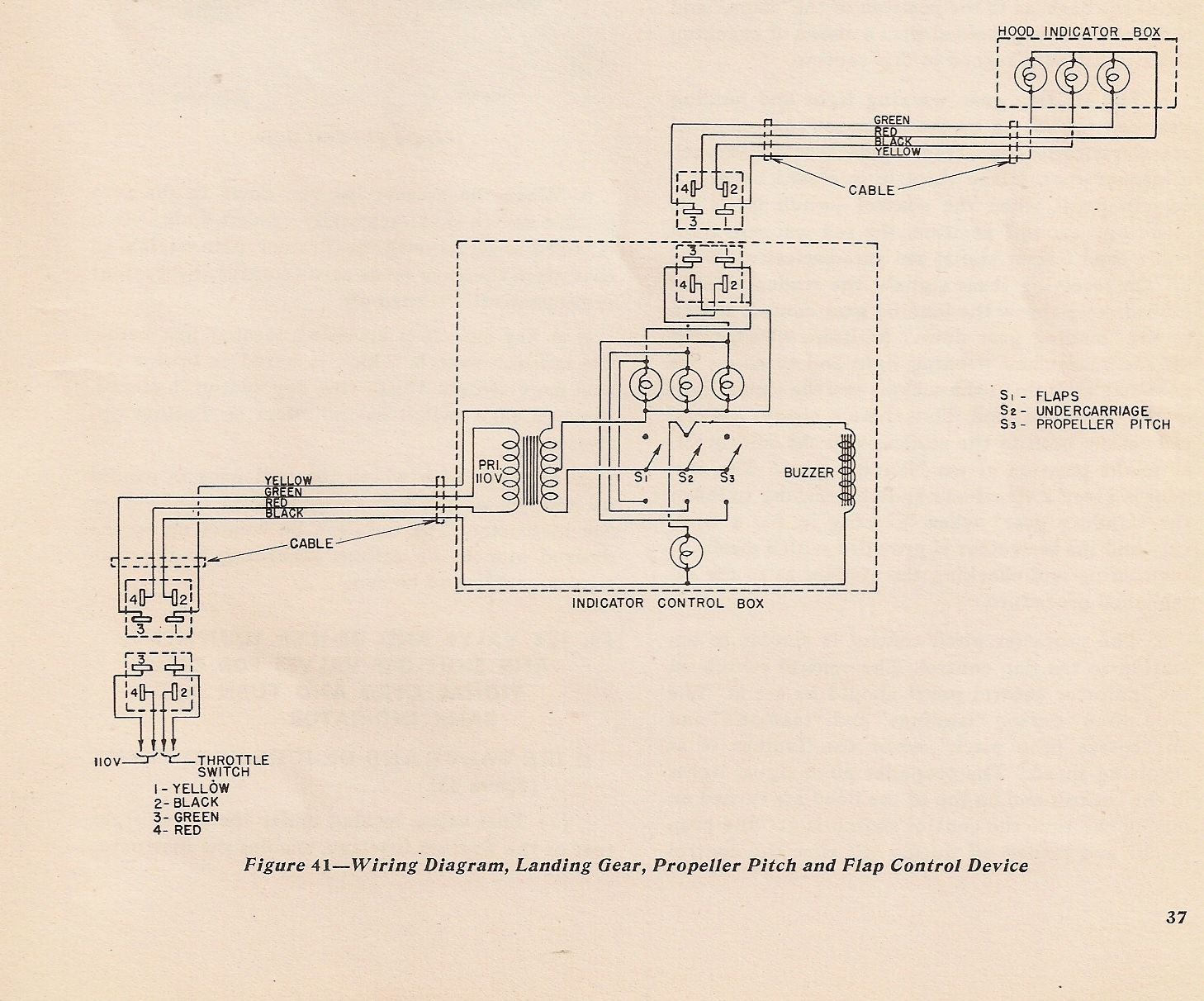
These systems were primarily used during takeoff and landing operations and allowed students to practice standard landing procedures, including flap operation, landing gear handling, and propeller pitch adjustment. Visual and audible warning indications simulated realistic landing conditions during training.
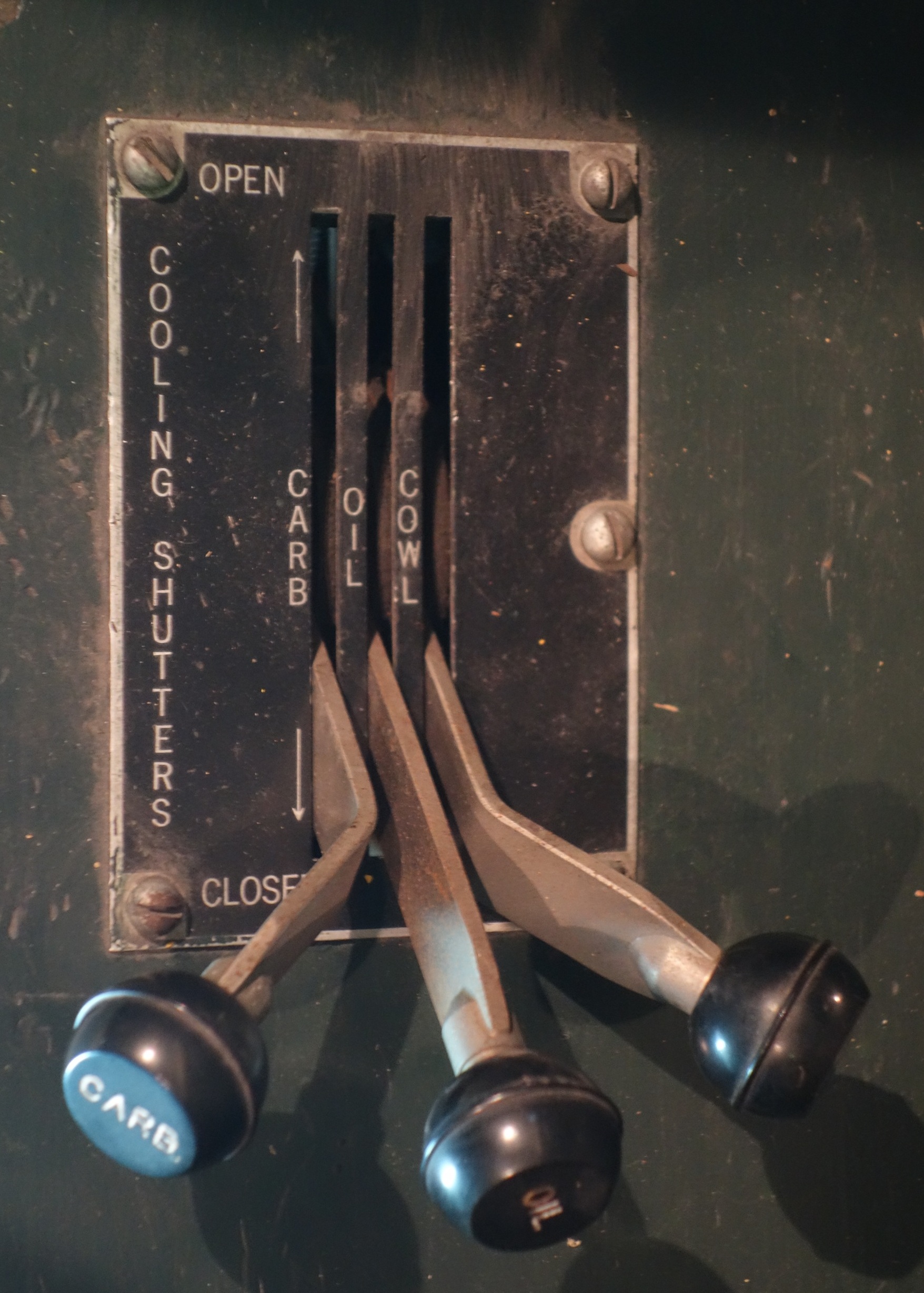
Cooling Shutters
The cooling shutter controls for the carburetor and oil systems are located on this panel.
They were used to regulate airflow and maintain proper engine and oil temperatures during operation.
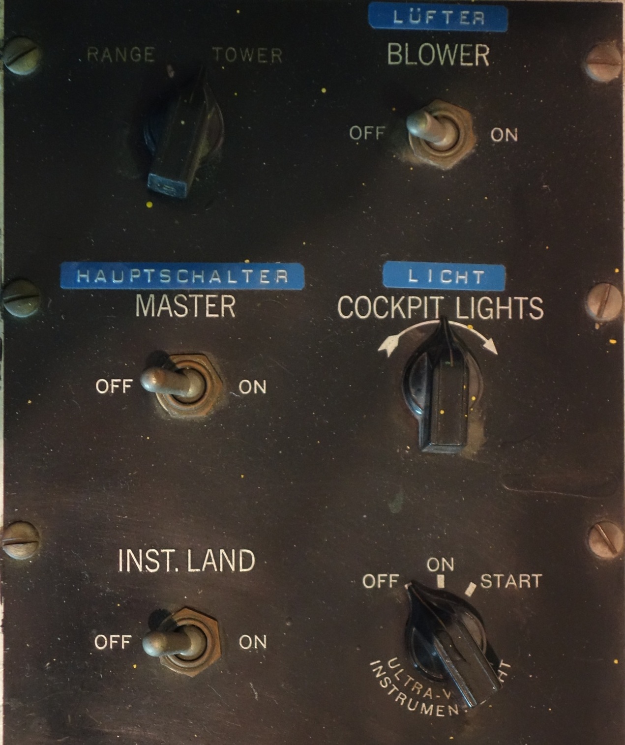
Switch Panel
Located to the right of the seat, this panel contains the main power, lighting, and ventilation controls.
It also includes settings for glide path functions, pitot heat, and the instrument landing system.
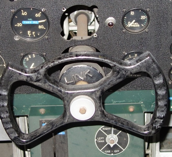
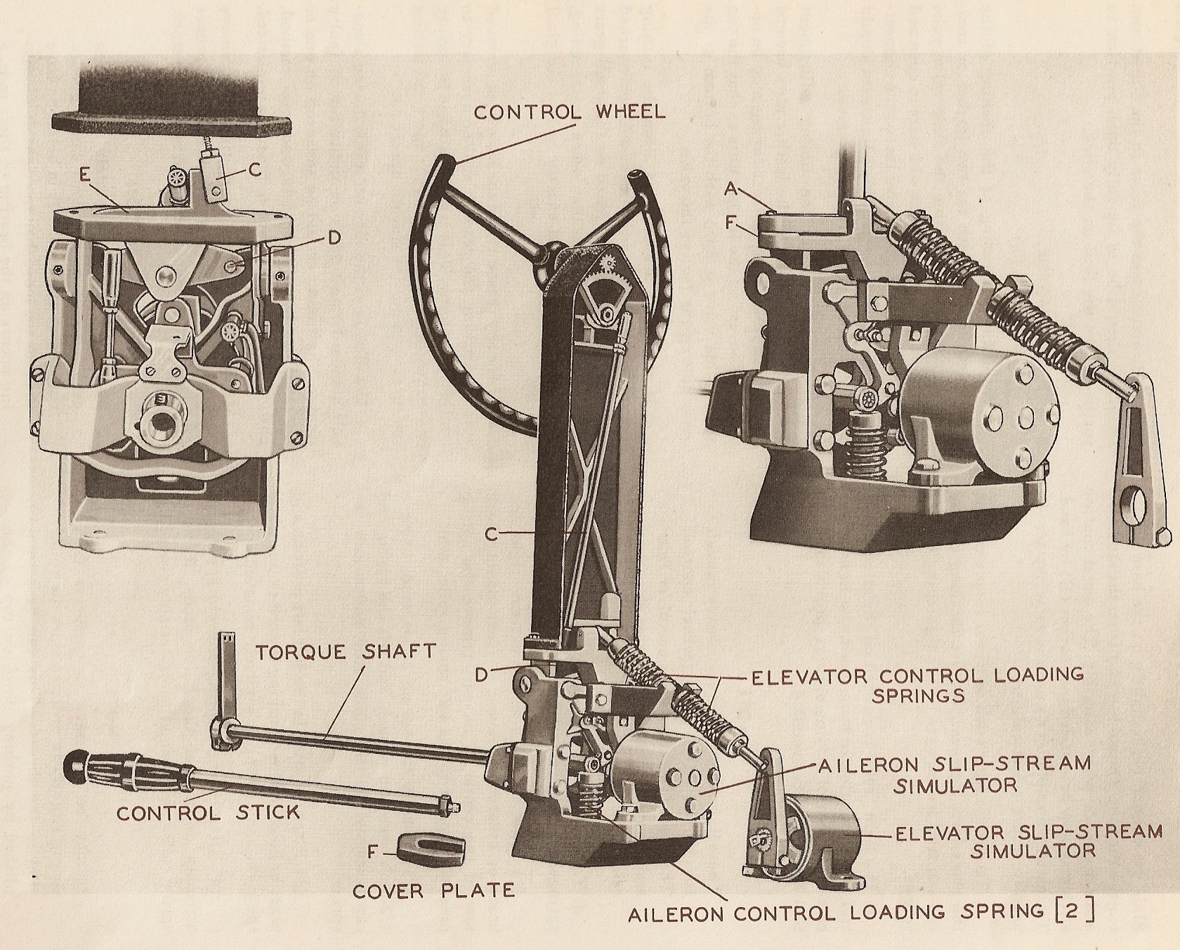
Yoke & Control Loading
The control yoke provides pitch and roll control, while the control loading system recreates realistic control forces and resistance experienced during flight.
In the original Link Trainer design, the yoke was mechanically connected to a system of vacuum-operated valves controlling the trainer’s motion. The aileron valve simulated banking movement around the longitudinal axis, while the elevator valve controlled pitching motion for climbing and diving.
Additional mechanical linkages introduced effects such as nose heaviness during turns and automatic banking behavior, demonstrating the remarkably sophisticated engineering used in early flight simulation technology.